 drud.cz
How to flash Sonoff S26 with Tasmota
Most of the smart electrical outlets are bound to their vendor “clouds”. That means you have to use some crappy apps provided by their manufacturers in order to control the outlets and usually there is no option to connect them to your custom home automation server. The good news is that there are some outlets which are relatively easy to “unlock” by re-programming to an opensource firmware. For example, various Sonoff devices based on ESP8266 chip can be updated to use Tasmota – a community-supported firmware that enables there MQTT protocol and Web command interface, so you can either connect them to your home automation server or control them directly by sending HTTP requests using curl.
In this post I’m going to describe how to upload a new firmware to Sonoff S26. It’s just a success story based on “How To: Flash the Sonoff S26 with Tasmota firmware” article with some additional details.
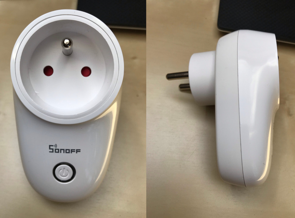
All right, this is how Sonoff S26 looks like (the EU-plug version):
Step 1: Disassembling
First, we need to remove 3 screws on this side:
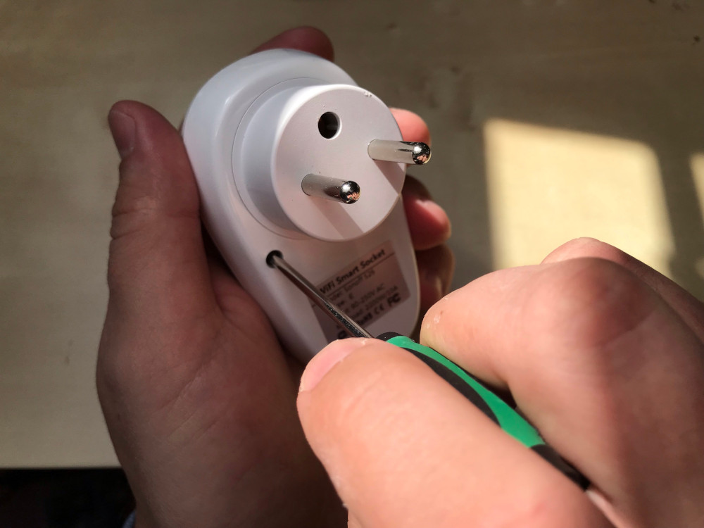
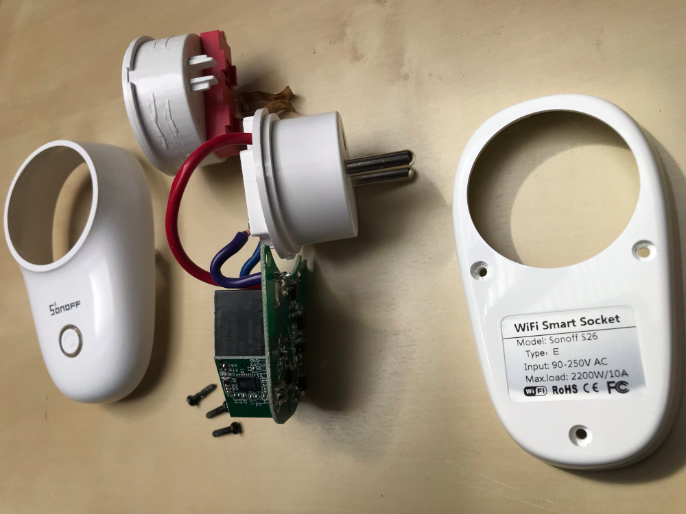
to open it and to get to the board:
Step 2: Soldering and Connecting to a USB-UART Programmer
Solder wires by the following schema and connect them to the USB/UART programmer (I used CP2102 USB-TTL UART 6-pin serial converter in my case):
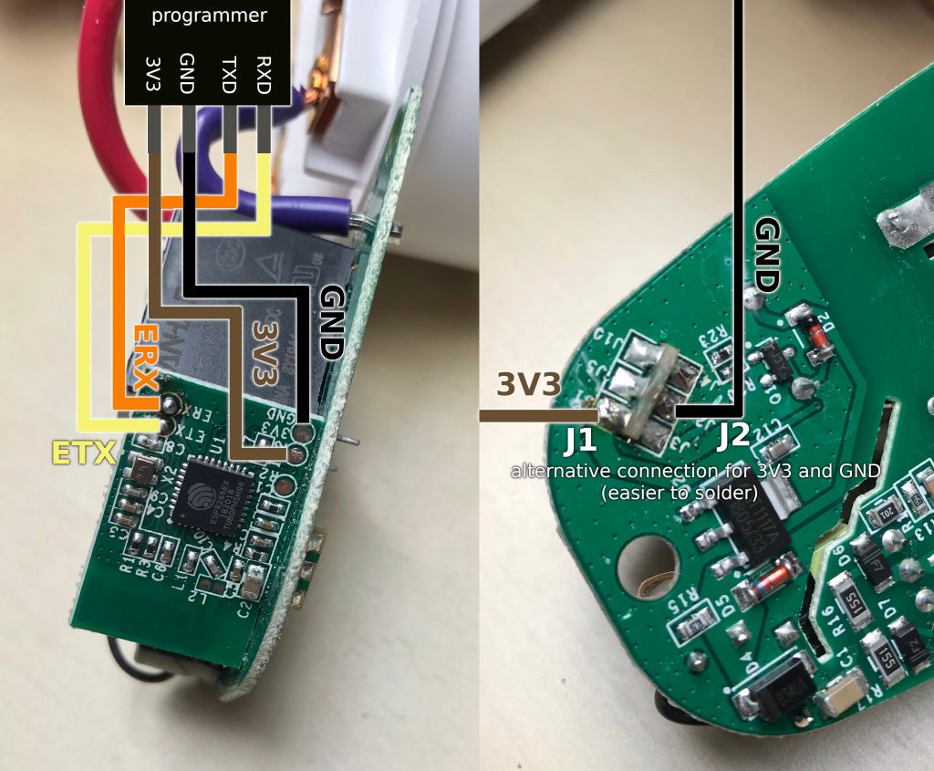
☝ Note that ETX is connected to RXD, ERX is connected to TXD.
☝ As an alternative, it’s much easier to solder 3V3 to J1 connector and GND to J2 connector as it’s shown on the right part of the image above.
I tried both variants and they all should work, so you can choose the schema more appropriate for you:
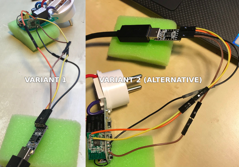
Make sure that the connections are strong, otherwise it might lead to issues during flashing.
Step 3: Install esptool
Now we need to install a tool which will communicate with the device. We will use esptool for this purpose.
It’s written in Python, so let’s setup a Python 2 or 3 virtual environment:
$ virtualenv esptool
$ source esptool/bin/activate
and install esptool there
(esptool) $ pip install esptool
Step 4: Check the Connection
The moment of truth has come and we can finally start communicating with the board. Before we connected the USB-UART programmer to a USB port of the computer, we should keep the button on the board pressed:
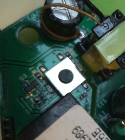
Then we can connect the programmer and release the button. I found it more convenient to use a USB extension cable instead of directly connecting the programmer to a USB port, so you don’t need to touch the programmer and can keep the soldered construction anywhere on the table.
Now let’s get a backup of the original firmware to check the connection.
☝ On my Linux machine the the programmer works on /dev/ttyUSB0 path. In your case it might be different: if you are on Windows, it can be, for example, one of COM1, COM2, etc., on Mac it can be something like /dev/tty.usbserial-.... So replace /dev/ttyUSB0 in all the commands below with the correct path for your machine.
(esptool) $ esptool.py -p /dev/ttyUSB0 read_flash 0x00000 0x100000 backup-original.bin
You will get something like:
esptool.py v2.6
Serial port /dev/ttyUSB0
Connecting....
Detecting chip type... ESP8266
Chip is ESP8266EX
Features: WiFi
MAC: 84:f3:eb:3e:56:bd
Uploading stub...
Running stub...
Stub running...
1048576 (100 %)
1048576 (100 %)
Read 1048576 bytes at 0x0 in 95.3 seconds (88.0 kbit/s)...
Hard resetting via RTS pin...
If you see something else (connection timeout or some other error), check the wires once again. Otherwise we can finally start flashing Tasmota.
Step 5: Flash Custom Firmware
Looks like the latest firmware for the moment (Sonoff-Tasmota v6.5.0) has an issue: S26 devices keep rebooting after few seconds. I tried it with 2 different outlets, and both had this issue. But the following image worked for me (Sonoff-Tasmota v6.1.1): sonoff-classic.bin. So you might use it as well.
We need to return the device back the programming mode. So unplug the programmer from the USB port, keep the button on the board pressed, connect the programmer back to the USB port and release the button.
Execute the following command (don’t forget to replace /dev/ttyUSB0 and the path to your firmware image):
(esptool) $ esptool.py -p /dev/ttyUSB0 \
                       write_flash \
                       --flash_size 1MB \
                       --flash_mode dout 0x00000 \
                       /your/path/to/sonoff-classic.bin
The output is gonna be something like:
esptool.py v2.6
Serial port /dev/ttyUSB0
Connecting....
Detecting chip type... ESP8266
Chip is ESP8266EX
Features: WiFi
MAC: 84:f3:eb:3c:7b:64
Uploading stub...
Running stub...
Stub running...
Configuring flash size...
Compressed 496368 bytes to 344076...
Wrote 496368 bytes (344076 compressed) at 0x00000000 in 38.9 seconds (effective 102.0 kbit/s)...
Hash of data verified.

Leaving...
Hard resetting via RTS pin...
Step 6 (Optional): Verify the Flashed Image
I didn’t trust the “Hash of data verified” message and decided to download the flashed image from the device to make sure it’s the same as the one that was uploaded there in the previous step before the wires get desoldered. Looks like some people had issues after successful flashing, but you might decide to skip this paranoid step ?.
If you want to verify your image, repeat the magic with unplugging-pressing the button-plugging-releasing the button once again to get the board back into programming mode and execute:
(esptool) $ esptool.py -p /dev/ttyUSB0 read_flash 0x00000 0x100000 flashed.bin
Since the downloaded image is 1MB and it is bigger than the original image, we need to get the size in bytes of the original image we flashed on step 5:
(esptool) $ du -sb /your/path/to/sonoff-classic.bin
496368	/your/path/to/sonoff-classic.bin
and compare only this length (in my case it was 496368) by the following command:
(esptool) $ cmp -n 496368 flashed.bin /your/path/to/sonoff-classic.bin && echo Ok
If you get Ok, then everything looks fine and we can go further, but if it shows that the first 496368 bytes are different, then it’s better to return to the step 5 and re-flash the image once again.
Step 7: Assemble Everything Back
Now we need to assemble all the parts back in order to try the device connected to 220V. I wasn’t able to preserve the soldered wires inside the case, since it’s pretty narrow there, so I had to desolder them.
⚠☠ I strongly encourage you not try to plug the outlet to a socket before covering the parts with the case, because it might be hazardous for your health, since you can accidentally touch conductive elements and get an electric shock.

Step 8: Configuring
Plug the assembled Sonos S26 outlet to a socket and quickly press the button 4 times to enable configuration mode. I had to repeat it few times until it eventually switched to this mode, since the button is not very responsive. Flashing light indicates that the configuration mode is on.
Take a mobile phone and connect it to the new ESP_XXXXXX open network established by the device:
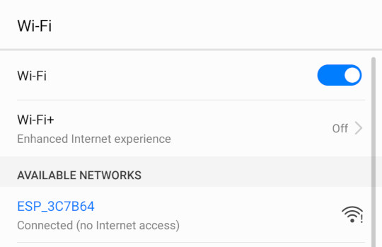
Open a browser on the mobile phone and navigate it to http://192.168.4.1 and enter the connection details for your normal wireless network:
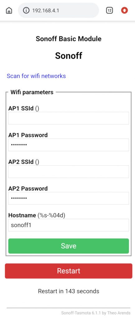
Save the configuration. The device will automatically restart itself.
Visit a wireless clients status page of your router to check if the device got connected and to figure out its IP address. Here is what I see on my router:
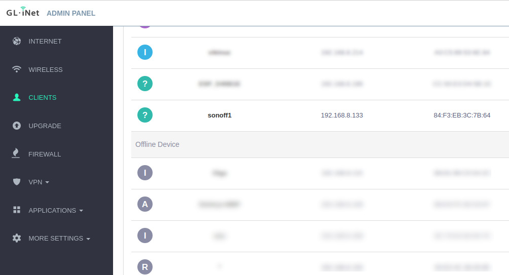
So in my case the IP address of the device was 182.168.8.133. Let’s send some test commands to make sure it works:
$ curl http://192.168.8.133/cm?cmnd=Power%20TOGGLE
{"POWER":"ON"}
$ curl http://192.168.8.133/cm?cmnd=Power%20TOGGLE
{"POWER":"OFF"}

 A feature of this router is that it works on